How to connect a SI1145 UV sensor to Arduino
Contents
Introduction
The SI1145 is an unexpensive, low-power, reflectance-based, infrared proximity, ultraviolet (UV) index, and ambient light sensor with I2C digital interface and programmable event interrupt output.
This touchless sensor IC includes an analog-to-digital converter, integrated high-sensitivity visible and infrared photodiodes, digital signal processor, and one, two, or three integrated infrared LED drivers with fifteen selectable drive levels.
The sensor also has visible and IR sensing elements so you can measure just about any kind of light . The SI1145 offers excellent performance under a wide dynamic range and a variety of light sources including direct sunlight.
You can use it with handsets, security panels, touchless switches, industrial automation and with a lot more application.
Specification
- Ultra-sensitive photodiodes with up to 3 independent LED drivers enable multiple functions
- Ambient light sensor
- Optional digital UV Index sensor
- Low-power sensors, signal processor, and ADC enable long battery life
- I2C interface for ease of communication with host MCU
- IR Sensor Spectrum: Wavelength: 550nm-1000nm (centered on 800)
- Visible Light Sensor Spectrum: Wavelength: 400nm-800nm (centered on 530)Tiny 2 mm x 2 mm clear QFN package
- Voltage Supply: Power with 3-5VDC
- Operating temperature: – 40 to 85 °C

Wiring
You can power the SI1145 from 3 to 5V DC, there's an onboard level shifter to safely bring the voltage down to 3.3V.
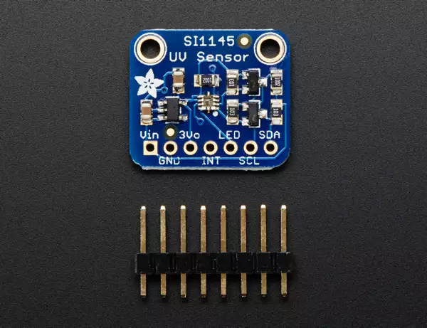
- Vin - this is the input to the voltage regulator. Power with 3.3-5V DC. Has reverse-polarity protection.
- GND - this is the signal and power ground pin, connect to your microcontroller ground pin.
- 3vo - this is the output from the onboard regulator. If you need a clean 3.3V DC, you can draw up to 100mA from this pin.
- INT - this it the interrupt output from the chip, with a 10K pullup to 3.3V. You can check this pin to see when the next set of conversions are done. Our library doesn't use it.
- LED - if you'd like to try using the proximity capabilities of the SI1145, you can tie an IR LED to this pin. Any IR LED will do. It's a open collector pin, so connect the cathode (-) pin to this pin, and the anode (+) pin of the LED to 3 to 5VDC. It can sink up to 300mA in a spike so be aware of that if using this pin.
- SCL - this is the i2c clock pin, connect to your microcontroller I2C clock master pin.
- SDA - this is the i2c data pin, connect to your microcontroller I2C data master pin.
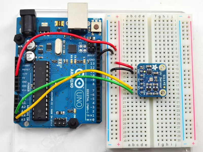
How to connect pins:
- Connect Vin to the power supply, 5V is fine. For 3V miccontrollers, connect to 3.3V
- Connect GND to common power/data ground
- Connect the SCL pin to the A5 Pin
- Connect the SDA pin to the A4 Pin

Example code
To begin reading sensor data, you will need to download the Adafuit’s exmaple from the following link:
Rename the uncompressed folder Adafruit_SI1145 and check that the Adafruit_SI1145 folder contains Adafruit_SI1145.cpp and Adafruit_SI1145.h
Place the Adafruit_SI1145 library folder your arduinosketchfolder/libraries/ folder. (Ex.: C:/Mydocuments/Arduino/Libraries/SI1145) You may need to create the libraries subfolder if its your first library. Now restart the IDE.
Open up File->Examples->Adafruit_SI1145->si1145test and upload to your Arduino wired up to the sensor and run the program to start your measurement.
References
- https://www.silabs.com/sensors/optical/si114x
- https://learn.adafruit.com/adafruit-si1145-breakout-board-uv-ir-visible-sensor/downloads
More information
- Connecting DHT11 temperature and humidity sensor
- How to connect an NFC reader to the Arduino
- How to connect a soil moisture sensor to your Arduino
- How to connect TMP36 temperature sensor to the Arduino
- Connecting US1881 Hall sensor to the Arduino
- How to connect a BMP085 pressure sensor to Arduino
- How to connect a TSL2561 luminosity sensor to Arduino
- How to connect a YL-83 Raindrop sensor to Arduino
- How to connect a Modern Device Wind Sensor to Arudino
- How to connect a SI1145 UV sensor to Arduino
- How to connect an Infrared Remote

 Sign in