UV exposure for PCB to prepare it for etching
Here you can learn how to use an UV exposure box to make your own PCB board. You can visualise the process through this helpful video and the step by step guide made from the video. Before you start you need a photoresist coated copper clad board to work on.

Step 1: Cut the board with a shear plate cutter
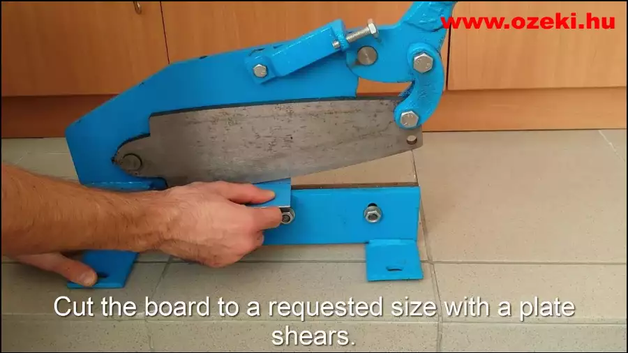
Previously you have determined the size of the board you would like to create. You need to cut the photoresist coated copper clad board to the required size. Just draw the cutting edge on the board with a pen, put it into the shear plate cutter. Carefully watch if the drawn line and the edge of the shear plate cutter perfectly aligns. Push down the handle by weighing on it (Figure 1).

Step 2: Remove protective film and place board into packet
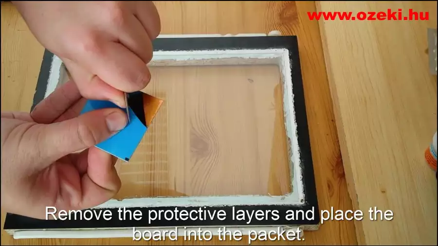
You will find a protective film on both sides of the board you have previously cut to the required size. Carefully remove protective film from the copper boards (Figure 2). Please do not touch the surface with anything. After you finished removing the film, slip the board into the packet you have previously created in the last tutorial.

Step 3: Place board between glasses
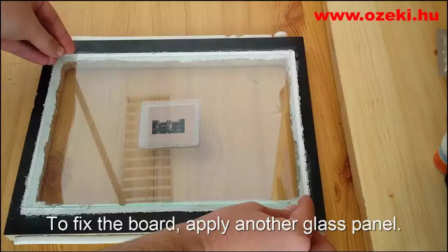
Now your board is in a packet. Please place the packet on a glass surface and install another glass panel on the packet (Figure 3). Check if your glass perfectly fits in the UV exposure box and is parallel with the UV lights. Make sure that the glass plates lay smoothly and closely to eachother.

Step 4: Place board into UV exposure box when ready take the board out
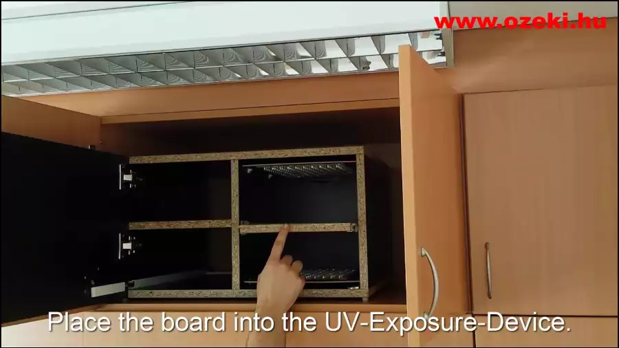
Now your board is between two glass plates. Slip the glass plates into the UV exposure box (Figure 4) and when you start lighting the board with UV do not forget to start measuring time. Make sure you determine the exact time your board needs to be exposed to UV light. You can find UV boxes with presettable timers for this purpose. When the UV exposure is ready you can take the board out. The next tutorial will show you how to develop and etch the PCB.

PCB UV exposure machine
The PCB UV exposure machine is a dark box with built in UV light. It is capable to illuminate your photoresist coated copper clad board from one or both sides. Machines that have UV leds on the top and bottom of the box can illuminate the board from both sides (Figure 4).
PCB UV exposure time
The PCB UV exposure time is the time you need for illuminating your board to make your PCB. The time depends on multiple factors like the exposure wavelength, amplitude (the luminous intensity of the wave), the number of leds, led diameter, the led light angle, the space between two leds and the distance of your board from the UV rays.
PCB UV exposure wavelength
The PCB UV exposure wavelength is the distance between the maximum amplitude of two neighbouring waves. The wavelength of your UV light should be from 390 to 400 nm. You can read the wavelength in the UV led datasheet. The required wavelength range is in the UV-A interval.
More information
- Printing PCB front and back layer
- Making the packet
- UV exposure for PCB to prepare it for etching
- Developing and etching

 Sign in