Controlling shades
Shades can make your room calm and protect it from heating up.
Remote controlled motoric shades can provide a comfortable solution, which is easy to use.
After fabricating the shades on your window frames, you can check the frequency on the boxing.
You can catch the 433 MHz signal data by connecting a small radio transceiver device to Ozeki 10.
This guide will teach you how to save these signals and retransmit them with the Scheduler. This application
comes free with your Ozeki software. With it you can set a time schedule to control the shades.
But if you wish you can do more complex tasks with the Robot Controller. Ozeki can detect light intensity or wind speed
with an analog sensor connection. Every time the wind blows too fast, the shades can go up
and all the time the sun shines too bright, the shades can be programmed to go down.
Section 1 - Build an RF transceiver circuit
STEP 1: Look how your shades work
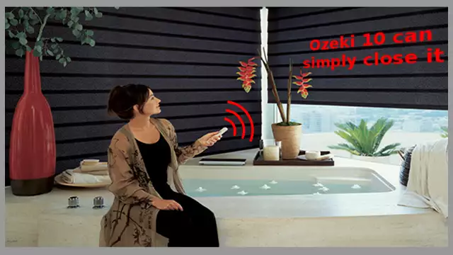
Most shades work with a remote controller. Try it and feel the motion how you can darken the room or let the sunshine in with the buttons. In this guide you will see how to imitate the signals with Ozeki 10 and how to build an easy little circuit. In the picture below you can replace the remote in the womans hand with a moisture sensor in the bathtub, which automatically detects if the bath gets above the required water level. If it is, the shades should close. Shades can use both 315 or 433 MHz. Find out which type of frequency your remote controller uses before continueing this tutorial.
STEP 2: Get all required parts
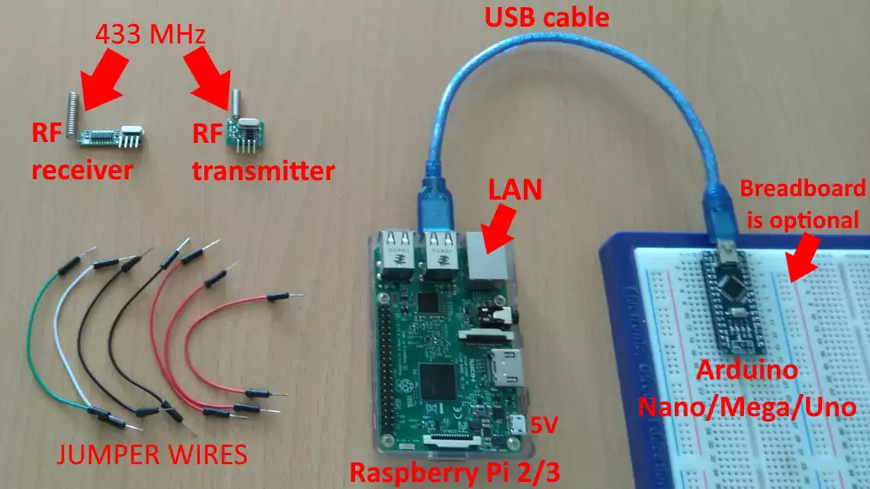
Get the required parts to automatically control your shades:- Raspberry Pi 2/3 (or Asus Tinker Board)
- Arduino Nano, Uno or Mega
- RF 315 or 433 MHz receiver, transmitter
- breadboard (to build your test circuit on)
- Jumper wires plus a USB cable
STEP 3: Look at the circuit diagram to see how to wire it
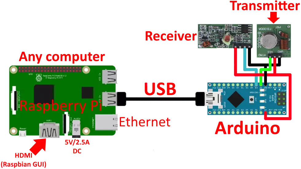
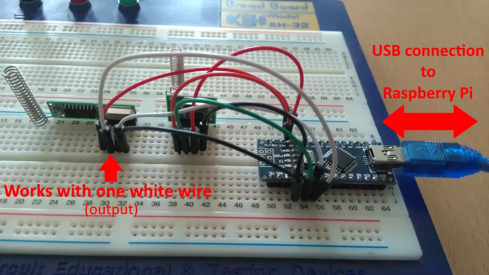
You can purchase all component on the internet and connect them on the breadboard the same way you can see it on the circuit below. Most users are already familiar with the Ethernet and USB, so let's focus on the jumper wires which connect the Arduino with the receiver or transmitter modules. The red wires transfer the 5V, while the black wires ground the 5V-s and this creates an electronical circuit in the modules. While the green wire on the circuit transfers outgoing data and the blue wire receives incoming data.
STEP 4: Build the radio transceiver test circuit
When you would like to do the first RF signal tests with Ozeki 10 or you are a beginner, it is a good idea to build the test circuit on a breadboard, which is really an optional component you can work on. It can be perfectly fit jumper wires as you can see on the photo below. The spiral antennas are quite aesthetic, although 17.3 cm long antennas are suggested for 433 MHz and 23.8 cm for 315 MHz frequencies. The antennas should be straight and made of copper wires, not as the ones you can find below.
STEP 5: Install Ozeki 10 to your Raspberry
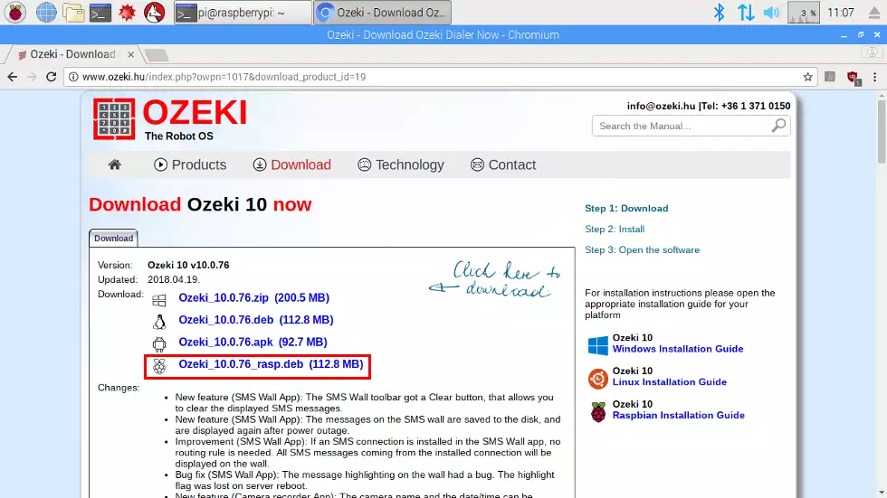
You will need to plug the Arduino to the Raspbian, but first install an Ozeki 10 server to the Pi as you can see it on the screensot. Here is the download link: http://www.ozeki.hu/index.php?owpn=231 where you should download the Raspbian package. There is a detailed installation guide on the following page: http://www.ozeki.hu/index.php?owpn=5986 which is a part of Ozeki 10's detailed user's guide. Read carefully to perfectly install it.
STEP 6: Download and install Arduino IDE
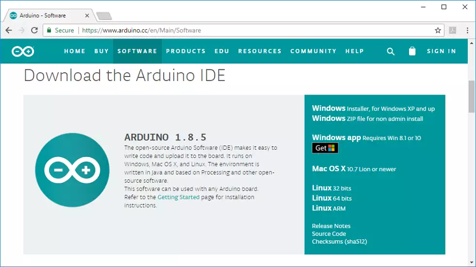
Now please find a Windows machine and make sure that Ozeki 10 is installed on it, although you do not have to activate it. Then install the Arduino IDE from: https://www.arduino.cc It is going to install all drivers for the boards as well. Keep in mind that all codes can be uploaded for other operating systems as well. If you look around the official download link, you can see what other operating systems that has supported installers.
STEP 7: Format microcontroller EEPROM
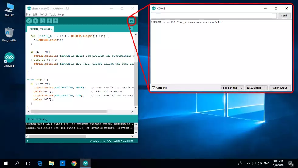
http://www.ozeki.hu/index.php?owpn=3110 This is an important page, which shows you how to format the EEPROM. It is highly important, because all devices have IDs, which are stored in the EEPROM, so it has to be clean to upload new devices. You can make sure that the EEPROM cleaner worked by watching the serial monitor on 115200 baud, which is the default baud rate of all Ozeki 10 devices. Look below to get it done with a simple click.
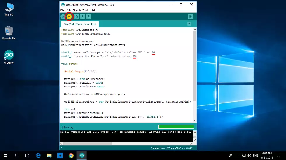
STEP 8: Load transceiver code to the microcontroller
http://www.ozeki.hu/attachments/5952/RF_transceiver_code.txt (copy)
The above code is really important, because it is the final code left on the Arduino's ATmega microcontroller.
It shows the pins correctly. The receiver pin is on D3 and transmits through the D2 pin. Both are digital pins capable to
transmit HIGH or LOW values at a single moment, but nothing between. This is how it can transmit or receive a defined number of bytes.
Section 2 - Take control over your shades with Ozeki 10
The only way to start is by connecting the circuit to the Ozeki 10 server you have installed on a Raspberry Pi. It is also shown in STEP 3's circuit picture. So please unplug it after the code uploading has been finished and replug it to the Raspberry Pi.
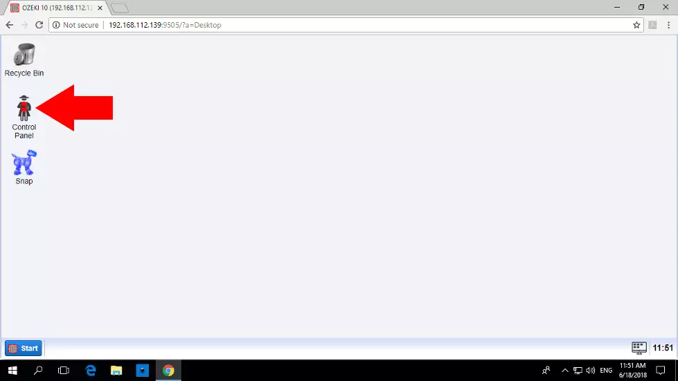
STEP 9: Open Control Panel from Ozeki desktop
You can open a webbrowser from any device on the planet and use the IP address of your Raspbian and port 9505 on the top of your webbrowser. Login with the same credentials you have used during installation and start the well known Ozeki 10 Control Panel as you can see it on the screenshot. Control Panel manages all Ozeki connections and the message flow too.
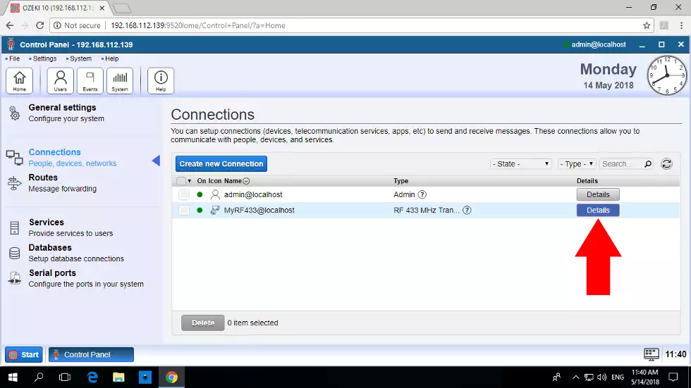
STEP 10: Click the RF transceiver connection
The transceiver will automatically added to the connection list, so you can click on it like below. If it doesn't appear on the list, you can connect to the port from the 'Serial ports' list, which you can find on the vertical toolbar. It is also advised to turn on autoconnect from the 'Config' tabpage from the same place you have wandered to after clicking the 'Serial ports' tabpage.
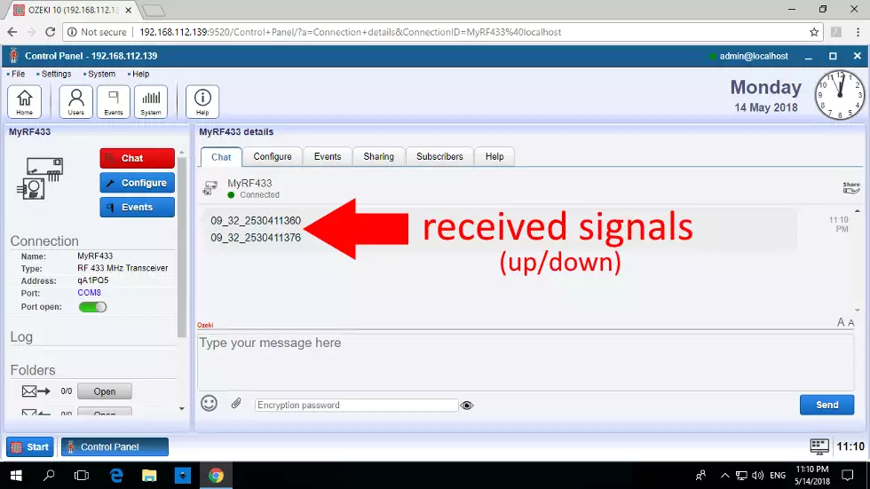
STEP 11: Save up/down signals from the shade remote
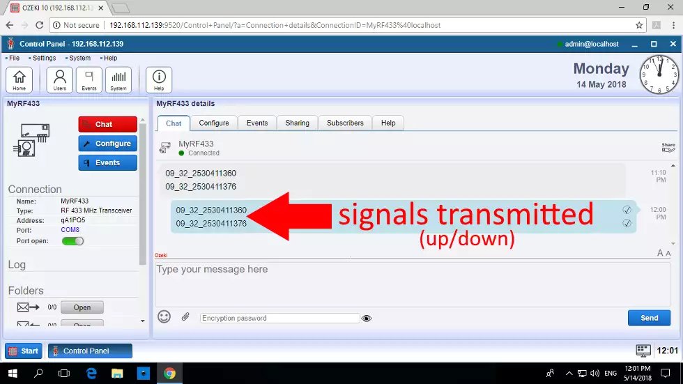
To test the receiver, it is really important to take the remote controller in your hand and press both up and down arrows. Finally look the Ozeki GUI for incoming messages. You will see both messages arrive in the chat window. These are basicly serial communication signals received through the air.
STEP 12: Retransmit saved signals
Now let's get to the interesting part. Please repeat the received signals by copiing them from the chat window and pasting them below it. Then please hit ENTER to transmit it. You should see the shades in front of your window moving up or down depending on the signal leaving the transmitter module.
Section 3 - Ozeki Task Scheduler can control your shades
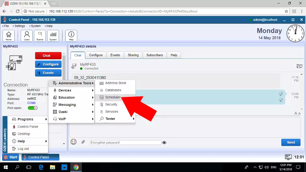
STEP 13: Open the Task Scheduler application The key is that you know how fine the shades are working with Ozeki 10. Ozeki has a start menu similar to Windows where you can open the Task Scheduler to set when your shades are going up or down. Although this guide only discusses one method, you can also make small codes to control your shades with Snap or the Robot Controller application, but let's just focus on the Task Scheduler to add a daily schedule in this tutorial.
STEP 14: Schedule a job to pull shades up
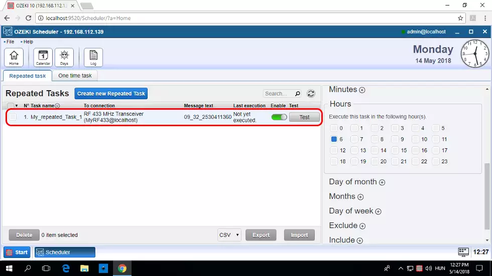
There is a big blue 'Create new Repeated Task' button on the appearing home page. Here you have multiple forms where you can select the RF 433 device from the connection box and add the shade pull up message. This can open your shades in the morning, so for example you can select 6 am like in the picture below. If you click 'Ok', you can save the settings and it should appear in the task list. Press test to make sure it pulls up shades.
STEP 15: Schedule a job to let down the shades
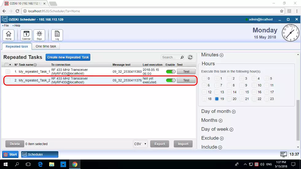
The same technique works for letting the shades down in the night, although make sure to use the proper signal that let's all shades down. After you create it, you can test it and make sure if it works by pressing the grey 'Test' button just right to the task that appears in the list. A great way is to think about your life plans and modify the shade schedule accordingly.
Sum up the technology
The RF transmission technology with Ozeki 10 has a much wider aspect as you can imagine. It is capable to move your garage motor, RF controlled remote lamps or control power outlets. But back to the topic of this page: shades. It is a great way to control all shades in the room by imitating the radio signals of the central remote or you can control them one by one too.
