The is a modified Arduino Nano, that was built to controll ultrasonic sensors. This is an open source board, with all the files needed for manufacturing. You may also freely modify the design.
Video 1 - How measures distance from an ultrasonic sensor

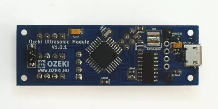
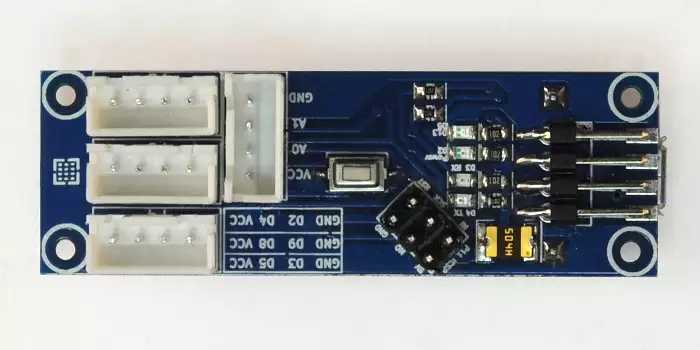
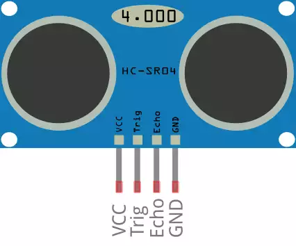
The contains an ATmega328P microcontroller so you can program it just like an Arduino Nano using the Arduino IDE environment. It has a micro USB port, which is compatible with mobile phone USB cables. It was designed to make it easy to control ultrasonic sensors, and it has standard mounting holes for M2 screws. You can connect a maximum of 4 HC-SR04 ultrasonic sensors to it. The ultrasonic sensor pins from left to right are: Vcc, Trig, Echo and GND (for help you can find a HC-SR04 datasheet below).

|
Download files for manufacturing
|
|
Datasheets
Tutorials
Examples
|
Specifications:
- IC: ATmega328P
- Clock Speed: 16 MHz
- Flash Memory: 32 KB
- SRAM: 2 KB
- EEPROM: 1 KB
- USB support provided by a CH340G USB to serial chip:
- Micro USB (compatible with mobile phone USB cables)
- Connection to the Ozeki HUB Controller
- Power supply from USB (5V)
- 500mA resettable fuse
- Status LEDs: power, TX, RX, D13
- 4 ultrasonic sensor connections
(Vcc, Trig, Echo and GND from left to right, which are used on HC-SR04 sensors) - Can be screwed on an Ozeki Matrix Board
- Product dimensions:
2.40in.[60.96mm]×0.80in.[20.32mm]
Pinout of the :
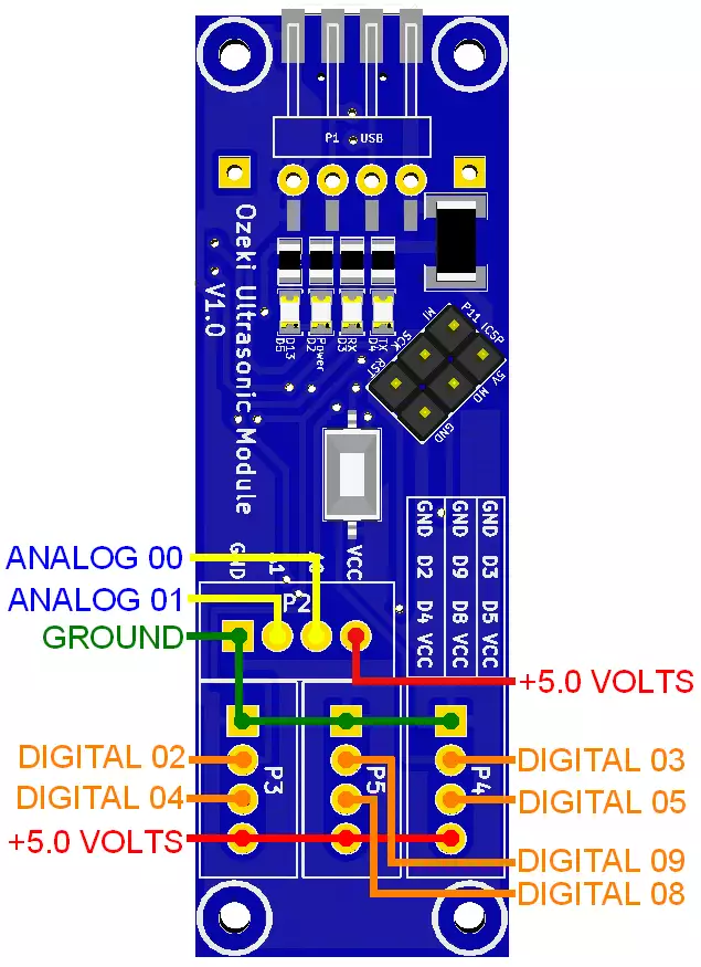
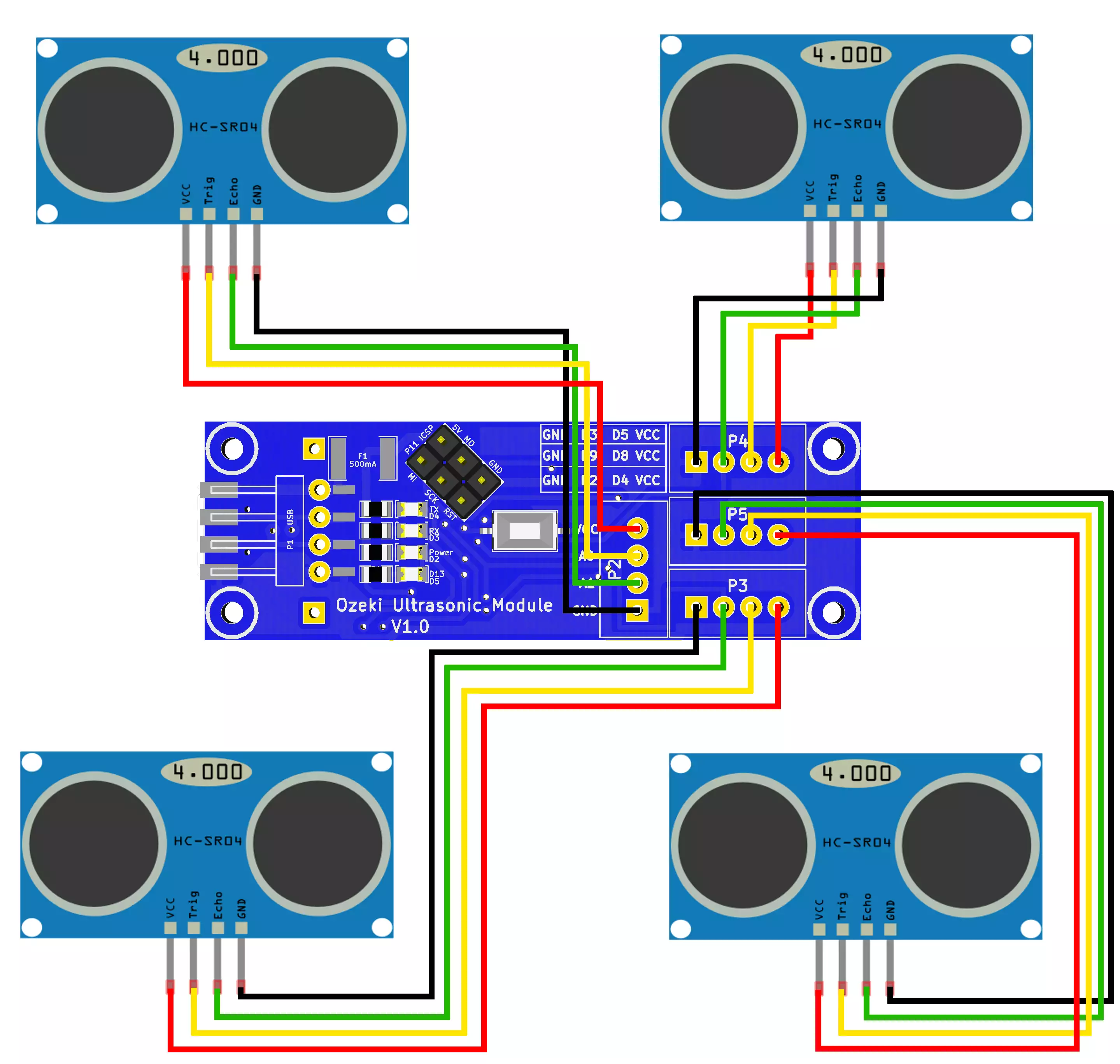
The pinout for the HC-SR04 sensor connections:
| HC-SR04 | VCC | Trig | Echo | GND |
| 01 | 5V | A0 | A1 | GND |
| 02 | 5V | D4 | D2 | GND |
| 03 | 5V | D5 | D3 | GND |
| 04 | 5V | D8 | D9 | GND |
The pinout of the HC-SR04 ultrasonic sensor:
The Trig pin will be used to send the signal and the Echo pin will be used to listen for returning signal.
Wiring:
Connect the ultrasonic sensors to the Ozeki Ultrasonic Module as shown below. Before wiring the ultrasonic sensors to your Ozeki Ultrasonic Module we suggest to solder a JST header strip to the following 4 pin count connector, as you can see in the image above.
Program codes
A code that measures distance from 4 sensors
This code allows you to connect a maximum of 4 ultrasonic sensors to the Ozeki Ultrasonic Module. If they are connected you will be able to measure the distance of objects from all 4 sensors. Distance is measured in cm. You can choose to connect less sensors as you can see in the video below.
Do not forget to ad NewPing.h to your Arduino libraries which you can usually find at
C:\Users\user\Documents\Arduino\libraries
You can find the newest versions of NewPin.h on the Arduino website.
Downloadable code:
UltrasonicModuleExampleCode.zip
Video 1 - How to measure distance from an ultrasonic sensor? Code is included below.

#include <NewPing.h>

#define SONAR_NUM    4
#define MAX_DISTANCE 200
#define PING_INTERVAL 33

unsigned long pingTimer[SONAR_NUM];
unsigned int cm[SONAR_NUM];
uint8_t currentSensor = 0;

NewPing sonar[SONAR_NUM] = {
  NewPing(A0, A1, MAX_DISTANCE),
  NewPing(4, 2, MAX_DISTANCE),
  NewPing(8, 9, MAX_DISTANCE),
  NewPing(5, 3, MAX_DISTANCE)
};

void setup() {
  Serial.begin(115200);
  pingTimer[0] = millis() + 75;
  for (uint8_t i = 1; i < SONAR_NUM; i++)
    pingTimer[i] = pingTimer[i - 1] + PING_INTERVAL;
}

void loop() {
  for (uint8_t i = 0; i < SONAR_NUM; i++) {
    if (millis() >= pingTimer[i]) {
      pingTimer[i] += PING_INTERVAL * SONAR_NUM;
      if (i == 0 && currentSensor == SONAR_NUM - 1) oneSensorCycle();
      sonar[currentSensor].timer_stop();
      currentSensor = i;
      cm[currentSensor] = 0;
      sonar[currentSensor].ping_timer(echoCheck);
    }
  }
}

void echoCheck() {
  if (sonar[currentSensor].check_timer())
    cm[currentSensor] = sonar[currentSensor].ping_result / US_ROUNDTRIP_CM;
}

void oneSensorCycle() {
  for (uint8_t i = 0; i < SONAR_NUM; i++) {
    Serial.print(i);
    Serial.print(". sensor");
    Serial.print(" = ");
    Serial.print(cm[i]);
    Serial.print("cm \t");
  }
  Serial.println();
}
Other modules
All of the Ozeki Processing Modules have ATmega328P or ATmega2560 microcontrollers integrated. Ozeki Modules can be connected to eachother like pieces of blocks. The connection is provided through USB to each module. They have M2 screw holes to give you an option to screw them on an Ozeki Matrix Board.
AutoConnect Link
If Ozeki 10 is running on your computer (such as on a Raspberry Pi) and you have plugged a microcontroller to it than Ozeki can be set to find serial devices on windows/linux and place them into a connection list so you can interact and control them through the software GUI.
